Individual assignment:
This week was about connecting and communicating different or same microprocessors/projects. After Neils' lecture I went through some literature regarding protocols in communication and I want to quote that information below.
Introduction
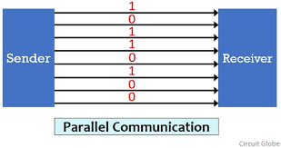
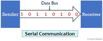
There are two methods used to transmit data between digital devices: serial transmission and parallel transmission. Serial data transmission sends data bits one after another over a single channel. Parallel data transmission sends multiple data bits at the same time over multiple channels.
The protocols for serial data transfer can be grouped into two types: Synchronous and Asynchronous. A synchronous serial interface always pairs its data line(s) with a clock signal, so all devices on a synchronous serial bus share a common clock. Asynchronous means that data is transferred without support from an external clock signal.
I2C
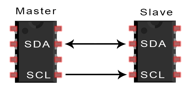
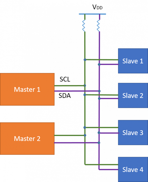
I2C (Inter-Integrated Circuit) is a serial communication protocol. I2C is synchronous, the output signal(bits) is synchronized to the sampling of bits by a clock signal shared between the master and the slave. So I2C only needs 2 lines for communication. SDA (Serial Data Line) and SCL (Serial Clock line).
Examples for I2C communication: 12x6 LCD Interfacing , Between two arduino boards etc.
Other commonly used communication protocols are Universal Asynchronous Reception and Transmission (UART) and Serial Peripheral interface (SPI). For my work I did I2C protocol.
My Literature References [1] [2]
‣ Intorduction to My Work
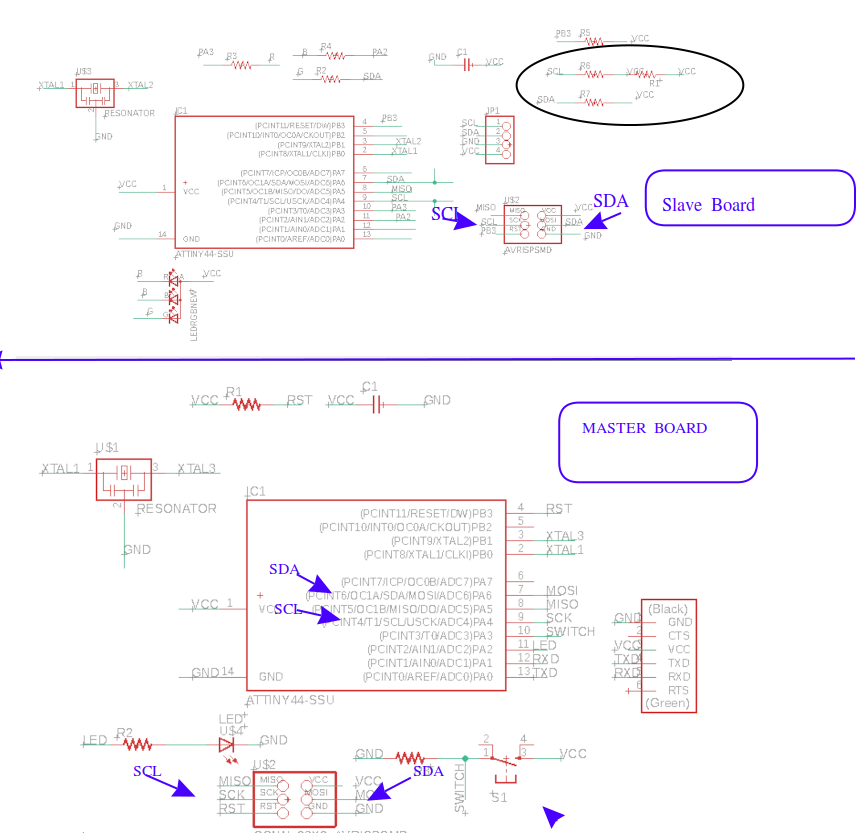
For my assignment I decided to communicate two of my previous boards. But i understood that any pull resistor should be there between VCC and SDA or SCL line either in master or slave board. But I couldn't find any apt board fulfilling this conduction. So I changed my mind to do communication between my board from week_6 electronic design- Echo board and Output board board from Eldho’s Output week
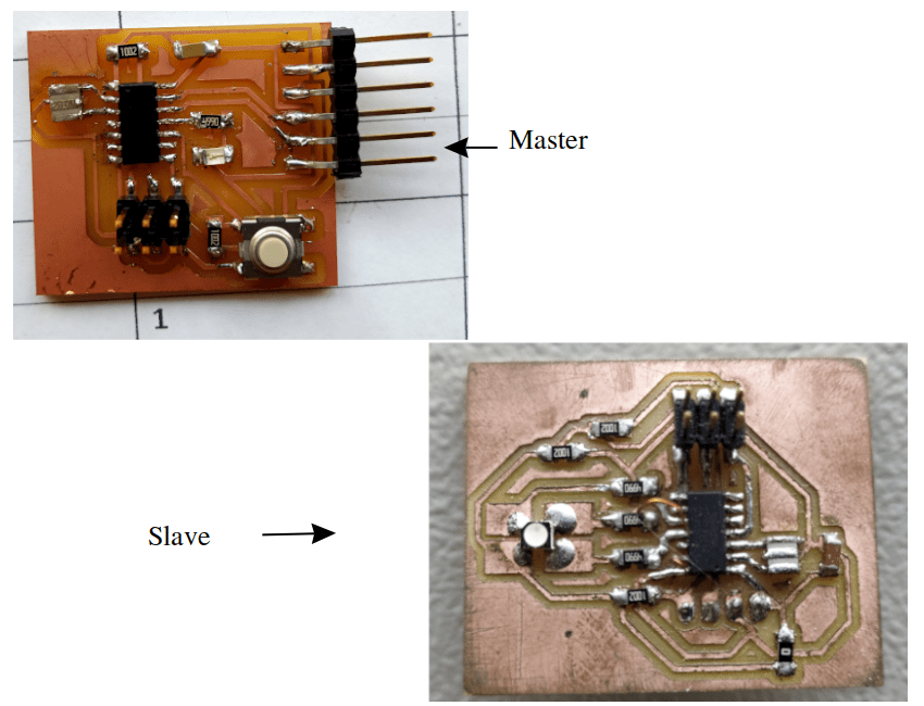
Below image shows the SDA and SCL port of slave and master boards
‣ Programming
Arduino IDE is used for programming boards. For I2C communication we need to install Wire.h to arduino library. The Wire library allows you to communicate with I2C devices. So I wrote programme in such a way that when switch is HIGH for master board a signal will be sent and RGB led will be HIGH Both programmes are compiled and uploaded.
Master Program
                    #include < Wire.h>
                    #include< SoftwareSerial.h>
                    #define button A3
                    #define led1 A2
                    SoftwareSerial mySerial(1, 0); // RX, TX

                    void setup() {
                      pinMode(led1, OUTPUT);
                      digitalWrite(led1, HIGH);
                      delay(2000);
                      digitalWrite(led1, LOW);
                      mySerial.begin(9600);
                      mySerial.println("Start");
                      Wire.begin();
                      pinMode(button, INPUT_PULLUP);
                    }

                    void loop() {
                      int data;
                      data = digitalRead(button);
                      mySerial.println(data);

                      if (data == 1)
                      {
                        digitalWrite(led1, HIGH);
                        Wire.beginTransmission(8);
                        Wire.write(1);
                        Wire.endTransmission();

                      }
                      else {
                        digitalWrite(led1, LOW);
                        Wire.beginTransmission(8);
                       Wire.write(0);
                        Wire.endTransmission();

                      }


                      delay(500);
                    }
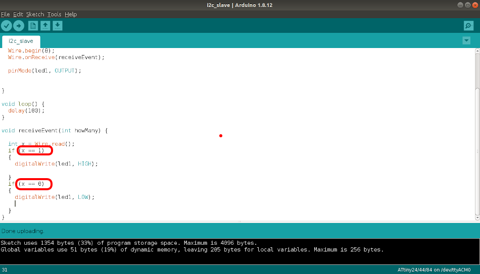
Slave Program
                        #include < Wire.h>
                        #define led 2
                        void setup() {
                          Wire.begin(8);
                          Wire.onReceive(receiveEvent);
                          pinMode(led, OUTPUT);

                        }
                        void loop() {

                          delay(100);
                        }

                        void receiveEvent(int howMany) {
                          int x = Wire.read();

                          if (x == 1)
                          {
                            digitalWrite(led, HIGH);
                          }

                          if (x == 0)
                          {
                            digitalWrite(led, LOW);
                          }
                        }
Compiling and uploading program using Arduino IDE. Since RGB LED is common anode connection we get low in RGB led when Master board switch is high.
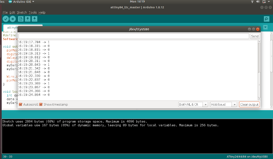
I also used a serial monitor for diagnosing any error . My boards communicated properly and video is shown below.
My Working Video
Lessons Learned
Here I want to make note of a mistake that I made earlier. In previous boards I couldn't add pull up resistors between SDA, SCL lines. So I was forced to take a board from Fab mate- Eldho Kurian.
Group Assignment
Link to week13- Networking and communication grop assignment page